Troubleshooting
The following section lists common problems and their solutions, beginning with an explanation of the Controller's LED indicators:
What are the Controller's LEDs telling me?
MSC Status LEDs
The ETC logo will illuminate when power is applied to the Controller. The red LEDs on the top/front of the Controller indicate the unit’s current status:
- The Active LED illuminates once the boot-up procedure has completed and is indicative of a fully functional unit.
- The Ethernet LED(s) indicates network activity (not network link) while the remaining LEDs indicate communication on the various ports of the Controller.
- The DMX (MSC), Output (MTPC, MSC) LEDs indicate that a valid project file has been loaded from the memory card and that playback has started.
MTPC Status LEDs
The Status LEDs on the MTPC are located on the front under the magnetic overlay and on the back next to the Ethernet connection.
- The Power LED illuminates to indicate that power is applied.
- The Active LED illuminates once the boot-up procedure has completed and is indicative of a fully functional unit.
- The Ethernet LED indicates network activity (not network link).
- The Output LED indicates that a show is loaded and eDMX data is being output. (Only on the front)
Error codes
The red status LEDs are used to indicate any boot failures of the Controllers or Devices that prevent the unit from going active.
MSC
The Ethernet, USB and MIDI LEDs will blink; the next three (Serial, Inputs, DMX) indicate the fault type:
- Serial on solid - SD card not present (insert or replace SD card)
- Inputs on solid - cannot mount filesystem on SD card (re-format or replace SD card)
- Serial & Inputs on solid - coprocessor fault (contact our support)
- DMX on solid - invalid hardware error (contact our support)
- Serial & DMX on solid - hardware fault (contact our support)
MTPC
The Active LED will be off (Power LED will remain on). Error codes are indicated by double flashing LEDs followed by a 1 second pause, the following combinations indicate the error:
- Ethernet & Output double flashing - memory card missing (insert or replace card)
- Ethernet & Output triple flashing - internal flash error (contact our support)
TPC-RIO
Error codes are displayed by a repeating pattern of flashing all four LEDs a number of times in succession, followed by a 1 second pause:
1 flash: Invalid firmware version (reload firmware from Designer) 2 flashes: Invalid device type or serial number 3 flashes: Internal memory test error 4 flashes: Unable to perform factory restore due to corrupt factory firmware 5 flashes: Current firmware is corrupt, no valid firmware versions available to restore 6 flashes: Restored firmware is corrupt
Codes 2 through 6 indicate a hardware error; please consult your distributor, representative or ETC Technical Services for assistance.
M-TS
These codes are outlined below and in all cases the Active LED will be off (Power LED will remain on):
- Ethernet & Output double flashing - memory card missing (insert or replace card)
- Ethernet & Output triple flashing - internal flash error (contact our support)
MSC X rev 2
Error codes are indicated by double flashing of the Ethernet M, Ethernet D, and Serial I/O LEDs, followed by a 1 second pause. The Active LED will also be off.
The bottom four LEDs indicate the error:
- DVI Input on solid -No SSD detected (contact our support)
- Output on solid - Corrupt SSD (recover via USB)
- Overtemp on solid - Invalid Hardware Type (reseat internal dongle)
Should the MSC X be unresponsive you can use the Controller Recovery or contact our Unison Mosaic Support Team for further assistance. Please note that the Recovery Tool may format the SSD and reinstall the firmware. In such a case all project data will be erased and so an upload will be required to restore programming.
MSC X Mk3
The Error LED in combination with other status LEDs is used to indicate any boot failures that prevent the unit from going active. In the event of a boot error, the Active LED will remain off, and the Error LED will illuminate with the following additional LEDs indicating the specific issue:
- Output -SSD Missing or Failed. Indicates the unit cannot detect or communicate with the SSD.
- Ethernet - SSD Corrupt. Indicates the unit can detect the SSD, but it does not contain a valid boot image.
- Output + Ethernet - Unable to communicate with front panel. Contact Support.
- Remote - Invalid hardware configuration. Contact Support.
Main board errors can usually be resolved by running the MSC X Recovery Tool on a PC. This may format the SSD and reinstall the firmware. In such a case all project data will be erased and so an upload will be required to restore programming.
Atlas
Error codes are indicated by double flashing of the Ethernet M, Ethernet D, and Serial I/O LEDs, followed by a 1 second pause. The Active LED will also be off.
The bottom three LEDs indicate the error:
- DVI Input on solid - No SSD detected
- Output on solid - Corrupt SSD - recover from USB
- Overtemp on solid - Invalid hardware type
Atlas Pro
Error codes are indicated by double flashing of the Ethernet M, Ethernet D, and Serial I/O LEDs, followed by a 1 second pause.
The bottom three LEDs indicate the error:
- DVI Input on solid - No SSD detected
- Output on solid - Corrupt SSD - recover from USB
- Overtemp on solid - Invalid hardware type
- DVI and Overtemp on solid - Graphics Driver overheated (contact our support)
EDN
1 flash: Invalid firmware version (reset to factory default required) 2 flashes: Invalid device type or serial number 3 flashes: Hardware fault with mezzanine card
1 flash: Invalid firmware version (reset to factory default required) 2 flashes: Invalid device type or serial number
MRIO
Error codes are displayed by a repeating pattern of flashing all four LEDs a number of times in succession, followed by a 1 second pause:
1 flash: Invalid firmware version (reload firmware from Designer) 2 flashes: Invalid device type or serial number 3 flashes: Internal memory test error 4 flashes: Unable to perform factory restore due to corrupt factory firmware 5 flashes: Current firmware is corrupt, no valid firmware versions available to restore 6 flashes: Restored firmware is corrupt
Codes 2 through 6 indicate a hardware error; please consult your distributor, representative or ETC Technical Services for assistance.
BPS
Error codes are displayed by a repeating pattern of flashing all four LEDs a number of times in succession, followed by a 1 second pause:
1 flash: Invalid firmware version (reload firmware from Designer) 2 flashes: Invalid device type or serial number 3 flashes: Internal memory test error 4 flashes: Unable to perform factory restore due to corrupt factory firmware 5 flashes: Current firmware is corrupt, no valid firmware versions available to restore 6 flashes: Restored firmware is corrupt
Codes 2 through 6 indicate a hardware error; please consult your distributor, representative or ETC Technical Services for assistance.
Why can't I see the Controller in the Designer Network window?
Presuming that the Controller has successfully booted its firmware The embedded operating system, stored in internal flash memory or on the memory card. (thus its Active LED illuminated) then there is a communication problem between the Controller and the PC running Designer:
Ethernet problems (network)
- Quit and restart Designer again once you're sure that the network is up, use your PC's LAN status tools.
- By default, the Controllers are set to obtain an IP address from a DHCP server, is there one on the network? Put one up and reset the Controller or set a static IP address via USB.
- Is the Controller's firmware compatible with Designer? Update it with the Recovery Procedure.
- Is there a firewall running on your computer or network? This could be blocking the multicast discovery packets.
- Are there any managed switches on the network? Traffic storms from 3rd party devices? Try "pinging" the Controller and other network debugging ploys beyond the scope of this document.
Ethernet problems (one-to-one)
- For a direct, one-to-one connection between a computer and the controller, you can, use a normal network cable because the network interfaces are auto-sensing.
- Quit and restart Designer again once you're sure that the is network up, use your PC's LAN status tools.
- By default, the Controllers are set to obtain an IP address from a DHCP server, is the PC running one? Set a static IP address for both parties, the Controller via USB. If the controller doesn't receive an IP Address from a DHCP Server, it will choose a 169.254.x.x address.
- Is the Controller's firmware compatible with Designer? Update it with the MTPC recovery procedure, the MSC recovery procedure.
Incorrect Ethernet cable (CAT5/5E/6) pairing
Not all electrical installers are aware of the subtleties of Ethernet cabling, in particular the correct pairing scheme. While incorrectly paired short cables may work, longer cables almost certainly won't or may exhibit intermittent errors. Note that simple continuity testers will NOT expose an incorrectly paired cable. See this Wikipedia topic for details.
Firmware Issues
For a Controller (or Remote Device) to appear in the network table, it must be on firmware version v2.x.x. If the controller is on firmware version v1.x.x, the Firmware Upgrade Tool can be used to upgrade the controller to v2.x.x.
NOTE: The migration tools stopped being updated in v2.5. These tools can be used to perform the migration, but a further firmware upgrade will now be required.
I can see the Controller in Network but it is shown in grey?
Controllers must be on the same Ethernet subnet as the PC running Designer. Select the controller and change it's IP settings accordingly.
I can see the Controller in Network but it is shown in red?
Controllers must be running the same version of firmware The embedded operating system, stored in internal flash memory or on the memory card. as the Designer software. Controllers with incompatible firmware will be highlighted in red. Select the Controller in the network window and press Reload Firmware.
Simulation looks fine but when I upload to the MSC nothing happens?
- Fixtures not patched. Try Output Live or examine the DMX Viewer to debug.
- Output Live left turned on (although a dialog now warns of this when uploading).
- The MSC or MTPC hasn't received a valid trigger to commence playback. Use the web interface to check status, examine the log and fire triggers.
Trigger conditions do not work in simulation, why?
Trigger conditions are not tested by the simulator.
Output Live does nothing?
- Fixtures not patched.
- The Output Live Mask has been incorrectly set.
The Controller's playback performance is deteriorating over time, why?
If your project has large numbers of timelines set to Hold or Loop, and these timelines are never explicitly released, then over time they will build up in the background and cause the Controller to struggle. Program your triggers to ensure that such timelines are explicitly released when no longer needed.
Uploading was working OK but now always fails?
The memory card has become corrupt and must be formatted, use network configuration or the web interface.
The controller doesn't load the project, why?
Sometimes a project file can be corrupted during transfer and cause the controller to reset shortly after booting. The controller tracks this and will prevent the project file from being loaded so that the controller can still be accessed. Review the project for potential errors and try to upload over a stable connection.
When I try to Upload I see a list of issues instead?
Designer will check things like triggers and hardware configuration to make sure that there are no inconsistencies. If any issues are found, the Issues tab will be opened automatically and a description of each issue will be listed so that you can take corrective action, see Issues.
Is there a way of seeing what the Controller is doing?
Yes, Controllers generate a log which can be viewed either via the web interface or from within Designer using the Controller Log in the main menu:
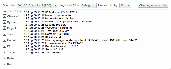
See Log viewer for more details.
I have forgotten the Controller's password?
You will need to go on site and gain access to the Controller then contact support for further instructions.
When using DMX In on a MSC, is my DMX line terminated?
No. To terminate the DMX line you should add a 120 Ohm resistor across the positive and negative terminals.
I can connect to the controller, but uploads fail
This is common with remote controllers when the Find function is used and is typically caused by only allowing connections to Port 80 of the controller. Designer also uses port 38008 to upload the project to the controller.
The web interface doesn't populate with data
The web interface uses Web Socket connections (RFC 6455), and some managed networks, internet security software and proxy servers block these connections. Ensure that your network and computer security allow this connection.
I have checked the FAQ and troubleshooting but I'm still stuck?
Contact support, please be prepared to send in your project file.