Each fixture has a variety of settings that control how Hog 4 OS handles it. Settings that control how the fixture as a whole behaves are configured in the Fixture window, while settings that are specific to individual parameters are configured in the Edit Fixtures window.
In addition to a fixture's patch information, the Fixture displays a number of important fixture attributes which are organized into separate columns. Some of these attributes are editable while others are read-only.
Notes can be used to create a note(s) for a fixture, such as its location or intended use. Notes can also be used when auto-generating palettes to quickly create groups based on notes.
To add a note to a fixture:
Tip: Fixture notes can be displayed in editors such as the Programmer, but this is turned off by default. To display notes, right click on any column header in the editor, and select Note.
Patch Notes can be used to attach a comment to a fixture regarding its patching.
To add a Patch Note:
The IP address column displays the fixture's IP address which is currently used for CITP and Video Patch records. The IP address column is read-only and is hashed out for fixtures that are not CITP capable or video patch capable.
When the "show details" button is enabled at the top of the Fixture window a column labeled Preview Package will appear. The preview package column allows the user to view / modify the selected preview package for a fixture. This is useful when there is a need to switch a fixture between a cached CITP preview package, a customized preview package, and/or the default library preview package for that fixture type.
When the "show details" button is enabled at the top of the Fixture window a column labeled Icon will appear. The icon column allows the user to view / modify the icon assigned to the fixture. Icons are used to represent the fixture when it is added to plots. Some fixtures in the fixture library already have an icon pre-defined for their fixture type when scheduled but can be customized by the user once scheduled.
When the "show details" button is enabled at the top of the Fixture window a column labeled Size will appear. The size column allows the user to view / modify the fixture's icon size. This is most useful when adding the fixture to plots.
When the "show details" button is enabled at the top of the Fixture window a column labeled Colour will appear. The colour column allows the user to view / modify the colour assigned to a fixture. Colour coding a fixture can help to make it easier to identify in the plot window.
Depending on a fixture's orientation in the rig, you may want to swap its pan and tilt axes. For example, if units are rigged facing across the stage rather than facing up or down stage, then swapping the axes keeps the Trackball movement and the fixture movement the same. This also ensures that fixtures selected in groups all move in the same direction as the Trackball is moved.
Fixtures that are rigged in other positions, for example on the stage floor as opposed to hanging, then combinations of swap axes and pan invert and/or tilt invert may be required.
To swap axes:
Depending on a fixture's orientation in the rig, you may want to invert its pan and / or tilt moment. For example, if units are rigged on the stage floor as opposed to hanging, then a pan and / or tilt invert may be required.
To invert pan and / or tilt:
You can use intensity percentage (also know as proportional patching) to change the intensity value output by the console to a fixture, relative to the intensity value that has been programmed. All intensity values for the fixture are reduced in proportion, so that with a proportional patch of 80%, a programmed intensity of 100% would be output as an intensity of 80%, and one of 50% would be output as 40%. You can use this to limit the maximum intensity of a fixture so that it never goes above 80%, for example, by assigning the proportional patch to 80%. Please note that reductions to the output of a fixture caused by changes to the intensity % value are not reflected in the values shown in the output window. This is because reductions to the fixtures intensity output are calculated in DMX only and therefore can only be viewed in the DMX output window.
To assign a fixture's intensity % (proportional patch):
You can assign a proportional patch value of above 100%. For example, if you patch at 200%, the intensity value that the console outputs will be twice that programmed. A programmed value of 25% will give 50% output, and 50% will give 100%. Programmed levels above 50% will not, regrettably, give fixture intensities above 100%.
Note that if you proportionally patch a fixture, its intensity will still be displayed on the console in the range 0 to 100%, even though the output value will be varying over the range defined by the proportional patch value.
When the "show details" button is enabled at the top of the fixture window a column labeled Col Cal will appear and shows whether the fixture has colour calibration data in the fixture library. You cannot edit this column, but it is useful to be able to check if the fixture is colour calibrated when working with the Colour Picker; see Working with Colour.
When a fixture's Cal Bypass option is toggled to "yes" then Hog OS will route virtual Red, Green, Blue function values directly to the fixture's physical red, green, and blue values without consideration for the fixture's native gamut.
When the Cal Bypass option is toggled to "no" for a fixture then Hog OS will use its internal color matcher system to calculate function values for all of the fixture's physical color mixing values based on the fixture's native calibration which may be generic or measured.
Cal Bypass cannot be enabled for fixtures with additional physical color mixing functions such as White or Amber additive color mixing functions.
Enabling Cal bypass is only recommended for fixtures that are set to a mode whereby the fixture is calculating its own physical function values based on incoming RGB or CMY values. For example, an ETC Source 4 LED Series 3 fixture set to RGB mode should be set to Cal bypass.
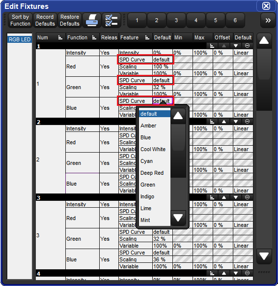
Additive Color Mixing functions have two features that can be adjusted in the edit fixtures window. These features impact how the console calculates physical color mixing values for the fixture when the virtual color mixing tools are used and vice-versa. Editing the default value of these features is only recommended when a fixture's color output does not match expected results.
The SPD Curve feature offers the ability to associate the function with a different spectral power distribution curve. The curves available include a series of generic curves with properties that generally match industry standard LEDs. The most common use case for changing the SPD Curve assigned to a function is to shift the LED's peak wavelength. Common examples include changing a blue SPD Curve to an indigo SPD Curve or changing a cool white SPD Curve to a neutral white SPD Curve.
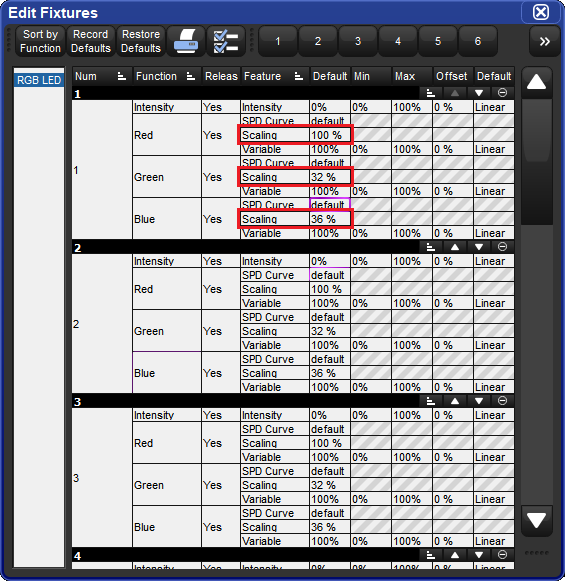
The Scaling feature offers operators the ability to indicate the real-world brightness of an LED in relation to the SPD curve. When scaling is set to 100% the implication is that the LED on the fixture matches the brightness of the SPD. Setting the scaling to a value of 50% implies that the LED is 50% as bright as the SPD curve. Please note that scaling cannot be set above 100%. While it is possible to achieve decent results through manual adjustment of SPD scaling, it is recommended to use the ETC Relative Brightness Calculator spreadsheet in coordination with a calibrated spectrometer to determine the most appropriate scaling adjustments for color accuracy.
Adjusting SPD Curve and/or Scaling defaults does not alter the relationship between the real-world value range of an Additive Color mixing function and the DMX Channel value. For example, even if the Red function scaling default is 60%, the operator can still achieve the full DMX range for the fixture's Red emitter through use of the physical Red function.
Changes made to SPD Curve and Scaling defaults are applied on a per fixture, per function basis.
When the "show details" button is enabled at the top of the Fixture window a column labeled Parkedwill appear and shows whether the fixture has any of its parameters parked in output. You cannot edit this column, but it is useful to be able to check if the fixture is parked.
You can configure settings that are specific to individual parameters in the Edit Fixtures window, as shown in the image below.
To open the edit fixtures window:
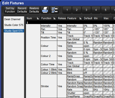
You can select a fixture type from the list on the left hand side of the window. The main part of the window then shows the configurable settings for each fixture of that type. The numbered buttons in the Jump Toolbar at the top of the window take you quickly to a particular fixture of that type.
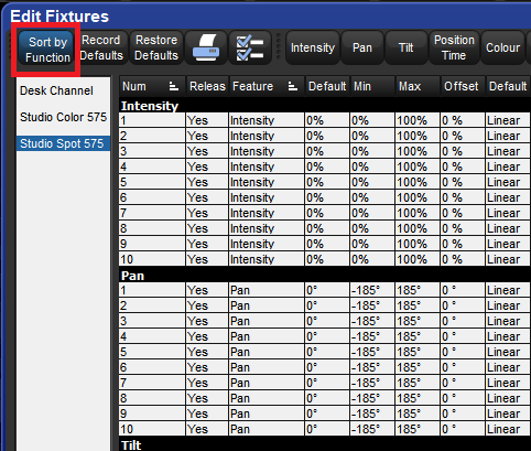
Pressing the Sort by Function button in the top left of the window changes the view, so that the main list groups each parameter together for all the fixtures of the type selected in the list. This is often the easiest way to work in the window, as you can easily click or press and then drag to select a range of cells to edit. For example, you could assign in one action the default value for the pan parameter of all the Studio Color 575 fixtures in the show.
When fixtures are placed close to obstacles, such as trussing or set pieces, it may be important to limit movement to prevent accidental damage, especially when the fixture is out of view of the operator. However, other functions can also be limited, for example to implement a house or event policy on the use of strobe lighting.
Note that limits can only be assigned for continuous parameters, not slotted ones.
To assign limits:
The default value is the value that the parameter will take when no playbacks or editors are controlling it. Fixtures also go to their default setting when the console starts up. There are three different methods for modifying the default values:
To modify function defaults directly in the edit fixtures window:
To modify function defaults using the programmer and record defaults button in edit fixtures:
Modify fixture parameters in the programmer to values that you desire as the default for that function on that fixture.
Setup → Patch → Edit Fixtures
Press the Record Defaults button at the top of the Edit Fixtures window.
Use the pop up dialogue to select which functions you want to modify the defaults for.
Enter
To modify function defaults from the command line:
Modify fixture parameters in the programmer to values that you desire as the default for that function on that fixture.
Record → Fixture
Use the pop up dialogue to select which functions you want to modify the defaults for.
Enter
To restore the fixture function defaults of one or more fixtures to their fixture library values:
It is important to note that the Restore Defaults operation only works on currently selected fixtures.
If no fixtures are selected then the Restore Defaults button will be grayed out.
This setting allows you to offset the range of values over which a parameter varies. For instance if one fixture is hung at an angle to the bar, so that it has a different pan centre-point from all the others on that bar, then you could assign an offset so that the fixture appeared to line up from a programming and operating point of view.
To assign a parameter offset:
Important: Applying an offset to a parameter after you have programmed values for it into your show will mean that those values will also be offset.
Some fixture parameters are continuously variable, for example CMY colour mixing. On the other hand some parameters, for example gobo or colour wheels, work in discrete increments or ‘slots’.
The Fixture Library loaded into Hog 4 OS defines the fixture's default slots, displayed on the Slot Toolbar, in palettes and the Programmer. When custom gobos or colours are used, you can customize the show file to display a suitable name for each gobo or colour slot, chosen from those in the fixture library.
To name a slot parameter:
Fixture parameters move to their default values when they are released. You can prevent specific fixture parameters from returning to their default values, so that they hold their current value until they are assigned to a new programmed value.
To set a releasable parameter: