Open topic with navigation
Energy Management
Energy management, when considering Paradigm lighting control systems, includes the collection of measured or calculated energy consumption data as well as the management of its connected loads through Demand Response load shedding. Energy management features are supported only in Paradigm Server Projects and only when the system, including the Paradigm Central Control Server (P-CCS), has been properly configured.
Energy data will be collected for each channel that is configured for monitoring and can be displayed on connected Virtual Touchscreens, P-TS18s, P-TSIs, or viewed using the P-CCS Web Interface. Summarized data can also be viewed on the Paradigm 7" Touchscreens. The P-CCS Web Interface can be used to generate downloadable reports of historical usage.
The collected data can be filtered and displayed graphically by the entire system, space, or group, and further filtered by the hour, day, week, month, or year. The P-CCS (via the Net3 Conductor portion) can store up to ten years of energy data for historical reference.
Configuring LightDesigner for Energy Usage
Energy usage monitoring starts with the configuration of load data for each channel in the Paradigm system, including Echo Zones associated with the system using Echo Expansion Bridges. The following instructions assume a system that has already been configured with Paradigm spaces, channels, stations, etc. The same configuration procedure applies to Echo spaces and zones.
These instructions are specifically tailored to assist with specifying the required properties for successful configuration of energy management.
-
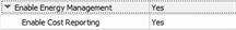
In LightDesigner, select the Server Project from the Browser and set its Energy Management property to "Yes". Additional properties display for specification including Enable Cost Reporting, and Currency.
-
If you are interested in knowing the estimated energy costs for the calculated and measured energy data collected, request your local energy costs from your utility provider. With the Server Project selected, and the Property Editor in focus, set the corresponding Enable Cost Reporting property to "Yes" and complete the additional costing properties that display.
- Measured energy data - Compatible ETC power control products (e.g. Sensor 3 with Advanced Features) can be configured to report measured energy data to the Paradigm system.
- Using Net3 Concert software, identify each circuit in your compatible power control product and configure, then note, its Net3 Space and Net3 Circuit properties. These properties must match the Net3 Space and Net3 Circuit properties for the related channel configured in LightDesigner.
- In LightDesigner, select a space and set the corresponding Net3 Space property in the Property Editor. Both the primary and sub-space must have a Net3 Space configured (acceptable range is 1-255) in order to receive measured energy data.
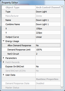
- Select a channel in the configured space and review the Property Editor, expanding the "Energy Usage" property. Set the Net3 Circuit value for the channel to match the measured power control product.
Energy Usage properties are set on an individual channel basis.
-
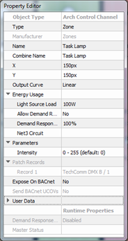
Calculated energy data - Individual channels (circuits or loads) in your system that are not controlled by a measured energy power controller, instead calculate their energy data based on values that you configure. If your channel is calculated, supply the following Energy Usage properties:
- Light Source Load - the maximum consumed by the load in watts at 100% intensity minus the Fixed Load value.
- Fixed Load -the minimum power consumed by the load, in Watts (present only in channels with non-intensity only values).
An ETC fixture that was added from LightDesigner's Fixture Library will automatically populate its Light Source Load (and applicable Fixed Load) data. Load information must be manually provided for all other channel instances.
Load information specifically related to calculations for Energy Management including Light Source Load, Net3 Space, and Net3 Circuit information can be uploaded by first configuring a single channel, then
exporting the load schedule, modifying the load schedule, then
reimporting the load schedule. This is recommended practice for systems with large amounts of channels to be configured.
- Upload the project to the Paradigm Central Control Server (P-CCS) and Paradigm Architectural Control Processor's.
- Log in to the P-CCS Web Interface and click the [Begin Energy Manager History] button to enable Energy Reporting collection. Energy data will be collected for each channel that is configured for either calculated or measured energy and can be displayed on a Paradigm 7" Touchscreen, on a connected Virtual Touchscreen, or viewed and reported from the P-CCS Web Interface.
To display collected energy data on a Paradigm 7" Touchscreen or a connected Virtual Touchscreen, the associated touchscreen configuration must include a button with an associated "Show Energy Manager" action assigned. Reference ControlDesigner online help for information to assign actions to buttons. When configured, associate the lcd configuration file to the desired touchscreen in LightDesigner and upload the project to the Paradigm Central Control Server and Paradigm Architectural Control Processors.
Systems using a P-TSI or VTS to view Energy Management on an external monitor must have a minimum resolution of 1280 x 768.
Configuring Demand Response for Load Shedding
Demand Response is a program created by an electric utility provider that enables partnership with customers to better manage operation of the electric grid by reducing or shifting their electricity usage during peak periods in response to time-based rates or other forms of financial incentives.
Demand Response is an integrated feature of a Paradigm Server Project utilizing the Paradigm Central Control Processor (P-CCS) by enabling the Demand Response property of each channel for inclusion or exclusion in the utility's demand response program. According to the configuration settings, a channel configured for inclusion in Demand Response can be set to turn off or can be limited to a maximum intensity level when Demand Response is remotely activated.
- In LightDesigner, select the Server Project from the Browser and set the corresponding Energy Management property to "Yes".
-
Select a channel, review the Property Editor and expand the "Energy Usage" property for the selected load.
Energy Usage properties are set on an individual channel basis.
- Set the "Allow Demand Response property to Yes. By default, the Demand Response Limit property is set to 100%, which means the, maximum intensity level for that channel is set to 100% by default. You will want to change this.
-
Change the Demand Response Limit property to reflect the output maximum. Setting this value to 0% will lock the channel at 0% output when Demand Response is active.
The Demand Response Limit property does not affect playback, manual level, master control levels, or preset activation statuses while in normal operation with demand response not active.
Paradigm supports standard actions to activate and deactivate Demand Response load shedding on individual spaces or groups, executable from a contact closure, UDP Serial Config, RS232 Serial Config, or the BACnet I/O Panel.