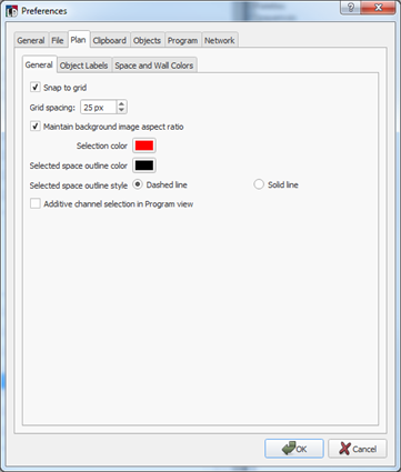
The "Plan" tab provides user selectable settings which affect how the Plan workspace displays data and graphics in the Design and Program/Simulate views. The "Plan" tab is split into three additional tabs settings including General, Object Labels, and Space and Wall Colors.
Settings within the "General" tab affect the Plan workspace in the Design and Program/Simulate views.

When the checkbox for "Snap to grid" is enabled in Preference, a grid pattern is displayed in the Design view. With the grid shown, objects (fixtures, stations, etc.), will align to the grid spacing.
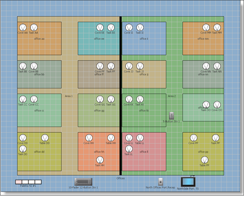
When "Snap to grid" is enabled in Preference, the grid is defaulted to a grid spacing of 23 pixels. Objects added in the Design view will snap to the grid with the specified spacing. Change the grid spacing using the increment or decrement buttons provided. You may change the grid pixel spacing to any value between 1 and 500 pixels.
Note: Changing the grid spacing setting after objects have been placed in the Design view will not automatically change the location of the existing object placement. Any new objects placed in the Design view will adhere to the grid spacing setting at that time. Additionally, moving any existing objects in the grid will adhere them to the grid spacing setting that is specified at that time.
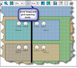
Tip: You can enable and disable "Snap to grid" while in the Design view by using the [Grid Snap] button located in the toolbar. Additionally, the grid spacing increment and decrement buttons are located next to the [Grid Snap] button for spacing changes as needed without the need to open the Preferences dialog.
 .
.
When the "Maintain background image aspect ratio" checkbox is enabled, the imported background image geometry will not be allowed to stretch from its native aspect ratio.
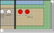
The selection preferences are indication of how you would prefer an object and space to be displayed when they are selected.
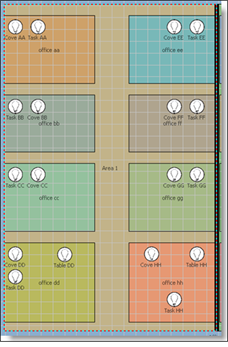
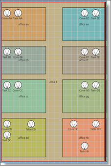
Settings within the "Object Labels" tab affect whether or not text labels are displayed for spaces, channels, and stations. To reduce clutter on the displays, labels can be hidden when the display is scaled below a certain zoom threshold. Additional settings include where the label is displayed in the space and the default font size with minimum and maximum settings as desired.
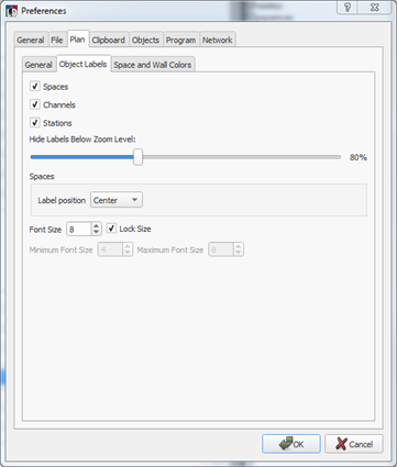
Click the check boxes to enable labels for "Spaces", "Channels" and "Stations" as they are displayed in the Design and Program / Simulate views.
Use the "Hide Labels Below Zoom Level" setting to define the zoom level at which object labels are hidden in the Plan workspace. Default setting is set for object labels to be hidden when the zoom level falls below 80%.
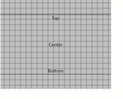
The "Spaces" section provides a "Label position" selection box to set the location of the space label as displays for each space in the Plan workspace. The label is centered both vertically and horizontally in the space by default. When "Top" is specified, the label shifts to fit in the top third of the space, when "Bottom" is specified, the label shifts to fit in the bottom third of the space.
The "Font Size" section provides the ability to set a defined font size for all object labels or set a minimum and maximum font size for use in conjunction with zoom levels.
By default, the "Font Size" is set to 8 points, with the "Lock Size" checkbox enabled. Enabling the "Lock Size" checkbox sets all labels to 8 points regardless of zoom level, except when the zoom level falls below 80%, or the defined "Zoom Level Setting" for labels.
When the "Lock Size" checkbox is unchecked, the "Minimum Font Size" and "Maximum Font Size" settings are enabled for edit. Set the minimum and maximum Font Sizes to the desired sizes.
Example: To make an example of this feature: Set the "Hide Labels Below Zoom Level" to hide labels at 80%, set the default font size to 8 points, the minimum size to 5 points and a maximum size of 11 points.
When the Plan workspace is at a zoom level of 100%, the label fonts will be displayed in 8 point fonts.
When the workspace is at a zoom level of 81%, the label fonts will be displayed in 5 point fonts.
When the workspace is at a zoom level of 200%, the label fonts will be displayed in 11 point fonts.
Settings within the "Space and Wall Colors" tab allow a user to specify default colors for spaces in the order they are generated.
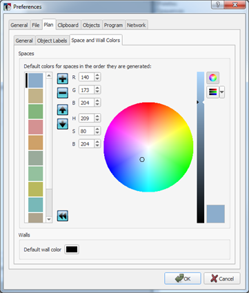
The column of colors displayed on the left of the dialog are the list of default colors that will be used for spaces in order they are created. You can change the default colors in the list as well as move the colors up or down the list using the tools provided in this dialog.
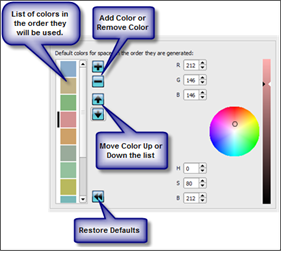
To add a color to the list, select the location where the new color will be in the list and click the [Add Color] button. Use the RGB, HSB, or color wheel to define the new color.
To remove a color from the list, click to select the color in the list then click the [Remove Color] button.
Rearrange colors in the list using the Up and Down buttons located in this dialog. Select the color to be moved, then click the [Move color up] or [Move color down] buttons.
Click the [Restore Defaults] button to restore the list of space colors to the factory defaults.