In some cases a fixture type may not be available in the full fixture library and is needed in a shorter time frame then can be delivered through a fixture request on the High End Systems website. Or it may be the case that the fixture you need to control is custom made or a slight variation of a popular fixture already in the fixture library. In these cases the fixture builder included in Hog 4 OS is a great way to build, export, and share fixture types. This section will cover how to create, build, and export fixture types in Hog 4 OS using the fixture builder utility included in Hog 4 OS v3.9.0 and greater.
Libraries can be built from a blank canvas or can be copied from existing fixtures within the library (when using V4 libraries).
To create a fixture type from scratch:
Open the fixture window (open + fixture)
Click on the button located at the top of the fixture window.
In the fixture builder window select the option from the current type drop down menu.
A new blank fixture type will be created and a set of tabs will populate along the left hand side of the window (Summary, Basic, Advanced, Functions).
Use the summary tab of the fixture builder to specify the fixture type's manufacturer, name, revision, author, and any notes you wish to add.
The fixture type's core dmx channel information, defaults, and options can now be created/edited using the basic, advanced, and function tabs. The best place to start is with the basic tab which is described in more detail in Fixture Builder Basic View.
In some cases you may need to create a fixture type that is loosely based on an established fixture type that is already available in the full fixture library. In this case it is recommended that you create a fixture type using data from an existing type using these steps:
Open the fixture window ()
Click on the button located at the top of the fixture window.
In the fixture builder window select the option from the current type drop down menu.
A window will pop up allowing you to choose an existing type from the Hog 4 fixture library currently being reference by the fixture scheduler.
Choose a fixture type from the list, then press the okay button.
Use the summary tab to make any desired adjustments to the fixture manufacturer, type name, revision, author, or notes. It is recommended to at least modify the fixture name to help differentiate it from the fixture it was copied from.
The fixture type can now be edited using the basic, advanced, and function tabs in the fixture builder. In most cases, altering and/or supplementing the copied fixture type data is most easy to accomplish using the advanced tab which is described in Fixture Builder Advanced View.
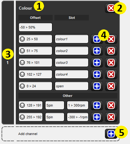
The basic tab of the fixture builder provides a simplified user interface for adding and modifying the basic dmx attributes of a fixture type. The first thing you will notice about the basic view are the large grey boxes labeled on the left with a number. These blocks represent the dmx channels of the fixture and are called dmx channel blocks. The diagram below shows the anatomy of a dmx channel block.
(1) Describes which function(s) are controlled by this channel.
(2) Removes the function definition and leaves the dmx channel block as "unused".
(3) Dmx channel number.
(4) Adds/Removes individual entries for the dmx channel.
(5) Adds a new dmx channel block to the fixture profile.
To add a new dmx channel block click on the blue plus symbol located in the "add channel" box.
To remove a dmx channel block click on the upper most red X button located in the dmx channel box.
To move a dmx channel block up or down, click and drag the dmx channel block.
To add/remove dmx entry use the blue plus and red x buttons within each dmx channel block.
When adding new dmx channel blocks to a fixture, the console will display a menu of template items that can be used as a starting point for defining each dmx channel block. In some cases a template may describe multiple dmx channel blocks depending the fixture attribute. For example, 16-bit intensity is a 2 channel function that occupies two dmx channel blocks.
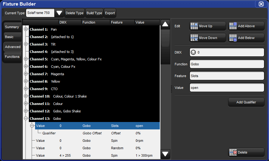
The advanced tab of the fixture builder provides a detailed and fully comprehensive view of a fixture type's dmx channel structure and allows for advanced editing of each dmx channel. Unlike the basic view, the advanced view give users access to every fixture function and feature supported by Hog 4 OS and allows for more complex relationships between fixture functions to be established through qualifiers (see Fixture Builder Terminology for details on qualifiers).
The advanced view organizes the fixture type's dmx channel information into a collapsible tree structure. The black aggregation bars with white text represent the dmx channels. Nested within each channel are dmx entries (function/feature definitions) that make up the channel. To the right of the tree view is the edit pane which provides a contextual interface with menus and buttons that update based on the selected row in the tree view.
To add a new dmx channel, select a pre-existing dmx channel aggregation header (white text / black background) and then press the add above or add below button in the edit pane.
To remove a dmx channel, select the dmx channel's aggregation header (white text / black background) and then press the delete button at the bottom of the edit pane.
To move a dmx channel up or down, select the dmx channel's aggregation header (white text / black background) and then press the move up or move down button in edit pane.
To add/remove/move a dmx entry select the dmx entry row in the tree and then use the coordinating buttons in the edit pane.
The functions tab of the fixture builder contains a summary of all of the function/feature pairings used in the fixture type and allows for customization of the following:
Some functions only have one feature while others have several. When more than one feature is used for a function, use the default feature column in the functions tab to establish the fixture's default feature for that function.
The "default value"column in the functions tab allows you to customize the default value for each function/feature pairing. The default value is used by Hog 4 OS to determine which real world value to revert to when the fixture is released. To edit a default value double-click on the cell containing the value, input the desired value, and press enter.
In some cases a fixture's dmx profile may not have a dedicated intensity channel but rather several dmx channels controlling the light output of the fixture. The most common example is when a fixture has red, green, and blue LEDs that combine to make "white" light. Hog 4 OS simplifies the control of these fixture types through a concept known as virtual intensity.
To establish virtual intensity for a fixture type, click the virtual intensity check-box option for each function/feature you want to include in the fixture's virtual intensity operation. For example, if you are building a fixture type that has I-Red, I-Green, and I-Blue functions, then clicking the virtual intensity option for each one of these functions will result in the console creating a virtual intensity function that controls all of these parameters together. When a fixture with virtual intensity is built, the virtual intensity function will simply appear to the programmer as "intensity".
![[Caution]](../images/caution.png) | Caution |
|---|---|
Intensity functions described with only a single dmx value are not eligible to be included in virtual intensity. |
To build a fixture type in the fixture builder:
Select the fixture type you wish to build in the fixture builder's current type drop down menu.
Press the button at the top of the fixture builder window.
The fixture type is now copied into current show file and can be scheduled using the fixture scheduler. If you wish to export the fixture type to a library for use in another show then please refer to Exporting Fixture Types to a Library.
Exporting a fixture type from the fixture builder into a new or existing library file is a simple process that allows you to stuff multiple custom fixture types into a single, portable, and sharable fixture library file.
To export a fixture type to a fixture library:
Open fixture builder and use the current type drop down menu to select the fixture type you wish to export.
Press the button at the top of the fixture builder window.
When the file browser pops up you can do one of two things:
(1) Type in a new unique name to create a wholly new fixture library that will contain just the single type you are exporting. Then press enter.
(2) Select an existing fixture library already installed in the libraries directory on the console. This will add the fixture type to that library. Then press enter.
The fixture type will now be exported into the new (or pre-existing) fixture library. If you wish to archive the fixture library for use on other console proceed to the next step.
Insert a USB flash drive into one of the USB ports on the console.
Open the shows window (, ) and select the file browser tab.
In the file browser, navigate to the library folder on the console's hard drive. Here you will find the fixture libraries installed on the console. Click and drag the desired fixture library from the library folder to the USB flash drive.
The console will prompt you to name the library archive. Give the archive a suitable name and press okay.
The fixture library is now archived on the USB flash drive an can be installed on any Hog 4 OS console running Hog 4 OS v3.9.0 or greater using the steps outlined in Download and Install Fixture Libraries.
To export fixture types from fixture builder to an XML file:
Press the button at the top of the fixture builder window.
Select the fixture type(s) you want to include in the XML file and press okay. Please note that fixture types copied from the fixture library are encrypted when exported and therefore cannot be edited using third party XML editor software.
Use the file browser to select a location for the XML file and press okay.
The resulting XML document can be viewed/edited on a Macintosh or Windows computer using a standard text editor or XML editor program. High End Systems recommends using an XML editor application that can validate the XML file using the Hog fixture library XML Schema Definition (XSD) which is referenced by all XML files exported by the Hog 4 OS fixture builder. Here are some cross-platform offline XML editing programs to consider:
Oxygen [www.oxygenxml.com]
Exchanger [www.exchangerxml.com]
XMLmind [www.xmlmind.com]
Fixture builder can import fixture types from XML files that are properly formatted and validated against the Hog fixture library XSD which is available online at [http://schema.hogfour.com/fixture.xsd].
To import an XML file containing fixture types into fixture builder:
Press the button at the top of the fixture builder window.
Select the XML file you wish to import using the file browser and then press .
All of the fixture types describe in the XML file are now copied into fixture builder.
A variety of terminology used in the fixture builder is described in this section.
DMX: represents the dmx value or range of dmx values that will output from the console when the specified real world values are programmed by the console operator. For example, a dmx channel entry with a dmx value of 0<255, a function of intensity, a feature of variable, and a real world value of 0<100% will result in a dmx output of 0 when the fixture's intensity is at 0%, a dmx output of 255 when the fixture's intensity is at 100%, and a variably scaled dmx value when the intensity is between 0% and 100%.
Function: represents the hardware component of a fixture that Hog 4 OS is attempting to control. In many cases the dmx protocol documents provided by a fixture manufacturer will list functions that are not available in fixture builder. In these cases a loose translation into an established Hog 4 OS function is required.
Feature: a sub-component of functions that further describes how the function operates in the fixture. Some functions may have multiple features. For example, Strobe is a function with multiple features including Rate, Random, and Random Sync. Function/feature pairings are the basic building blocks of a fixture type's dmx profile. Much like fixture functions, most manufacturers do not describe fixture features exactly the same as the Hog 4 OS fixture builder and a loose translation will be required.
Value: (short for real-world value) represents the programmable real world value or range of values for a given function. For example, slotted colour wheels are defined using real-world values such as "Orange" and "Congo" whereas a variable functions such as Intensity are described using real world values such as 0% and 100%. Fixture builder's pop-up menu system will suggest the most common real world value ranges but you should always attempt to input the real world values ranges that most accurately match the fixture's dmx channel documents.
![[Tip]](../images/tip.png) | Tip |
|---|---|
Each function/feature combination used in a fixture type must be defined on all dmx channels where that function is used. For example, if strobe/rate is used on dmx channel 9 and strobe/random is used in dmx channel 10, then strobe/rate must also be defined on dmx channel 10 and strobe/random must also be defined on dmx channel 9. |
Unused: if a dmx channel is unused Hog 4 OS will output a constant dmx value of 0 for the corresponding dmx channel when the fixture is patched.
Attached Channel: increases the dmx capacity of a function from 8-bit to 16-bit. For example, if dmx channel 1 is assigned to the Pan function and dmx channel 2 is attached to dmx channel 1 then dmx channel 1 will act as coarse control for Pan and dmx channel 2 will act as fine control for Pan.
Qualifiers: used to specify any conditions that must be met in order for a function/feature to output a specific value or range of values. Multiple qualifiers can be added to a single function/feature entry within a dmx channel. One example is a slotted colour wheel with offsets. In this case the main function/feature pairing is ColourOffset/Offset which is defined with dmx value range (such as 0<10) and a real world value range (such as -50% > 50%) and is qualified by ColourSlot/Index with a specific real world value (such as red). In most cases a dmx value is not required for qualifiers. Qualifiers can only be added/removed/edited in fixture builder's advanced view.
None: can be used as a dmx value to indicate that no changes will occur to the dmx output for a dmx channel regardless of whether the specified real world value conditions have been met.
ANY: can be used as a function, feature, or real world value.
When is used as a function the console will output the dmx value specified in the dmx channel entry regardless of any other conditions. Therefore, using as a function for a dmx channel entry results in that dmx channel outputting a constant dmx value. The option in fixture builder's basic view is the same as setting the function to .
When is used as a feature the console will output the dmx value specified in the dmx channel entry regardless of which feature is active in the programmer/playback. This similar to assigning to a function but allows for the function to specified on the dmx channel. This is not very common.
When is used as a real world value the console will output the dmx value specified in the dmx channel entry if the specified feature is active in playback/programmer.
![[Tip]](../images/tip.png)
Tip Fixture builder automatically creates coordinating cyan, magenta, yellow, hue, and saturation functions when I-Red, I-Green, and I-Blue constructs are described in a fixture's dmx channel description and have dmx value range of 0 thru 255 and a real world value range of 0% thru 100 %.
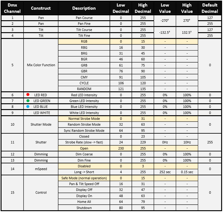
The following fixture builder tutorial provides step-by-step instructions for creating, building, and exporting a fixture type that is capable of controlling the essential functions of the High End Systems Uno fixture. Please refer to the DMX chart shown in the figure below as part of the tutorial.
Open the fixture window () and click on the Fixture Builder button located at the top of the fixture window.
In the fixture builder window, use the "current type" drop down menu to select
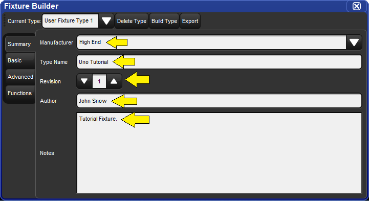
Select the summary tab in the fixture builder window and fill in the fixture information as shown in the figure below:
Select the basic tab in the fixture builder window.
Click on the red X located to the far right of the dmx block for channel 1 to remove intensity. Click OK to confirm the remove.
Click on the blue plus button for channel 1. A template menu containing common fixture components will appear. Refer back to the Uno Dmx chart and look at channels 1 through 4. The first thing you'll notice is that channels 1 thru 4 control the Pan and Tilt constructs of the fixture. You'll also notice that pan and tilt each occupy two dmx channels (one for coarse control and one for fine control of each parameter). This is known as 16-bit Pan and 16-bit Tilt. Press the 16 bit button listed next to Pan & Tilt in the template menu for channel 1. Notice how fixture builder automatically fills in channels 1 thru 4. Channels 1 and 3 are labeled as Pan and Tilt while channels 2 and 4 are attached to channels 1 and 3. This is how 16-bit channels are represented in fixture builder.
Next we need to defined the real world values for pan and tilt. Refer to the dmx chart. As you can see no adjustments need to be made to Pan as the Uno's values happen to match the template's pre-filled values. However, you will need to type in new real world values for Tilt (-132.5 < 132.5).
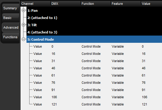
Now let's move on to defining dmx channel 5. Once again, refer to the dmx chart for the Uno. Here we see that channel 5 is defined as "colour mode". Since "colour mode" is not a native function in Hog 4 OS we must use an alternative function. In this case we will use "Control Mode". Since basic view doesn't have a "Control Mode" option in the template menu we need to switch to advanced view. Click on the advanced tab in the fixture builder.
In the advanced view you will see a tree view of all of the dmx channels that we've specified in the fixture so far. Now we are going to add and define dmx channel 5. Click on the black header for channel 4 and then press the Add Below button located in the edit menu on the right. This will add channel 5 to the channel tree.
Now we will add a series of dmx entries for channel 5. To add the first dmx entry press the Add Value button. Refer to the Uno's dmx chart. The dmx value of the first entry on dmx channel 5 is 0. Click on the dmx cell, input a dmx value of 0 and confirm by pressing the green check mark button. Next we will select "Control Mode" as the function, "Variable" as the feature, and 0 as the real world value.
Continue adding dmx entries to channel 5 using the "add below" button and fill in the appropriate values until channel 5 looks like the figure shown below.
Now let's go back to basic view and add a definition for dmx channel 6. Click on the Basic tab.
Click on the blue plus button in the "Add channel" rectangle to begin defining channel 6. Once again we need to refer to the dmx chart. Here we see that channels 6 thru 10 control the I Red, I Green, I Blue, and I White functions of the fixture. Let's quickly assign channels 6 thru 9 to these functions by choosing the RGBW component from the basic view's template menu. The fixture builder will automatically fill in the function definitions for channels 6 thru 9.
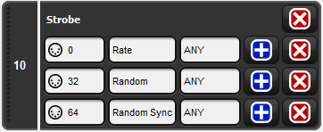
Now we move on to dmx channel 10. As you can see in the dmx chart, channel 10 is a shutter (strobe) channel. Press the blue plus button in the "Add channel" rectangle, then press the Basic button in the Strobe section of the template menu. This will auto-populate channel 10 with a few strobe function/feature combinations. Since these entries don't match the dmx profile of the Uno, we will need to edit them.
Refer back to the dmx chart. The Uno has three different strobe modes defined in channel 10. Each of these modes (or features) needs to be added to channel 10 in the fixture builder. Since these entries only establish the strobe modes (features) and do not specify a real world value, each entry should have a real world value of . Once you are finished, channel 10 should look like the figure below.
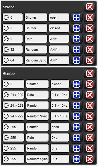
Now click on the blue plus button in the dotted "Add channel" rectangle to add channel 11 to the fixture. Refer to the dmx chart. As you will see channel 11 also controls the strobe function of the fixture but more specifically controls the rate of each strobe mode. Channel 11 also has a shutter open and shutter closed value. We are going to use the Complex strobe option from the template menu in basic view to establish a starting point for editing channel 11. Use the graphical interface in basic view to make dmx channels 10 and 11 to look like the figure below.
You might be questioning why we added a strobe/shutter definition to dmx channel 11 and channel 10. The reason is that Hog 4 OS must initialize every function/feature pair for all channels that refer to a specific function.
By now you should be getting the hang of adding and removing dmx channels and dmx entries. Let's move forward with adding and defining channel 12 using the 16-bit intensity component from the template menu. The reason we are using the 16-bit intensity component is because the fixture's intensity parameter is split into two dmx channels. Much like 16-bit Pan and 16-bit Tilt, the first dmx channel in the intensity's definition is for coarse control while the second dmx channel is for fine control.
Now we are ready to define channel 14 of our fixture which is mSpeed. Controlling the fixture's mSpeed value is NOT necessary since Hog 4 OS has it's own programmable timing for every function and feature. Therefore, channel 14 should be assigned to a "Constant" dmx value of 0. Select Constant in the template menu and set the dmx value to 0. This will ensure the fixture's mSpeed is always set to 0 seconds.
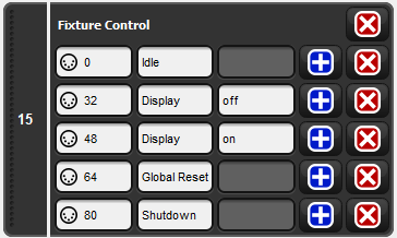
Finally we've reach channel 15. Look at the dmx chart. Channel 15 is a control channel. Click on the blue plus button in the dotted "Add channel" box to add channel 15.
Select from the template menu. Use the fixture builder basic view to edit the dmx entries for channel 15 so that they match the dmx protocol.
Congratulations! You have now finished defining all of the dmx channels of the Uno tutorial fixture.
Select the Functions tab of the fixture builder. The functions tab lists all of the fixture's functions and features in an easy to read spreadsheet. The default values and virtual intensity assignments can also be edited using the functions view.
The Uno has dedicated 16-bit intensity functions assigned to dmx channels 12 and 13, which means we do not need to add virtual intensity to the Uno profile. Un-check the virtual intensity option for all functions.
The default features and default real world values also don't need to be altered since the Uno's dmx profile matches the pre-populated default values provided by the console. However, it might be good idea to experiment with changing the defaults as a part of your learning experience with this tutorial.
The next step is to the build the fixture type so that it can be scheduled and patched in the current show file. Press the button located at the top of the fixture builder window. If fixture builder finds any errors a dialogue box will pop up and the build process will fail until you correct the errors.
When the fixture build succeeds a prompt will appear alerting you that the build was successful.
Open the fixture window and click on the "Fixture Schedule" button. Use the fixture schedule dialogue to search for the fixture type you created. It should show up as "Uno Tutorial" and be listed under the High End manufacturer. An icon indicating the fixture was built in the fixture builder will also be displayed next to the fixture name. Schedule and patch the fixture to the appropriate dmx output and begin testing the fixture profile with a real fixture if available. The dmx window is another way to verify the dmx output is working as expected when controlling the fixture.
Once you have tested the tutorial fixture you can export it to a fixture library so that it can be used across consoles and with different show files. To export the fixture type to a fixture library select the fixture in the fixture builder using the current type drop down menu and press the export button at the top of the fixture builder window. When the file browser pops up, select a name for the library and press okay. This will export the fixture type into a new fixture library which will be located in the library folder of the console.
To copy the fixture library to a USB flash drive go to the open the shows window (setup, shows) and select the File Browser tab. Drag the fixture library from the libraries folder on the console to the USB drive. You will be prompted to name the library archive. Give the library archive a name and press OK. The fixture library is now written on the USB flash drive. The library archive can be installed on any console running Hog 4 OS v3.9.0 or greater using the steps outlined in the Download and Install Fixture Libraries section of this help manual.
Althought the fixture builder does have an interface for building compound fixture types it is still possible to create and build compound fixtures using the XML import/export tools of the fixture builder and an offline editing using a simple text editor or XML editor application. Refer to the procedure listed below for instructions on how to create and import compound fixtures:
Launch a new or existing show.
Open the fixture window () and click on the Fixture Builder button located at the top of the fixture window.
Use the fixture builder to create fixtures that represent the parts of the compound fixture you wish to create. For example "Wash 1000 Master" type and "Wash 1000 Cell". Make sure all of these fixtures are built with the same manufacturer name.
Click the button at the top of the fixture builder.
Select the fixture types that will make up the different parts of the compound fixture you are building. Click .
Use the browser to select a drive location that you can easily access and click .
Open the exported XML file on a Mac or PC using a text editor or XML editor application.
Locate the last closing </Types> tag that appears in the document. This will be very close to the end of the document.
Copy and paste the following text after the final tag </Types> tag:
<CompoundTypes>
<CompoundType name="EDIT" revisionId="0">
<History revision="0" author="EDIT" date="2020-01-31" comment="EDIT"/>
<Origin>User</Origin>
<Icon type="circle" size="medium"/>
<Parts>
<Part number="0" type="EDIT" plotX="0" plotY="0"/>
<Part number="0.1" type="EDIT" plotX="0" plotY="0"/>
</Parts>
</CompoundType>
</CompoundTypes>
Replace the word EDIT in the pasted text with the appropriate values as described below:
The CompoundType name value is the name of the compound fixture that appears in the fixturer scheduler.
The type value for each compound fixture part must be the name of one of the types described in the XML document.
To add more parts to the compound fixture simply copy and paste a part definition and assign it to a part number.
Save the XML file once you are done editing. Please note that the XML file will fail XSD schema validation due to a lack of a UUID but this will not impact your ability to import the fixture type into a show.
Import the XML document into the fixture builder using the button.
Once the XML import is complete the compound fixture type and the individual fixture types included in the compound fixture will be available in the fixture scheduler. Please note that the compound fixture itself will not appear in the fixture builder. Editing the compound fixture requires editing the XML file and importing it to the fixture builder again.
