Fixtures must be patched in Eos and then added to an Augment3d model before they can be displayed and controlled. If you already know the position and orientation of your fixtures, you can manually add them to Augment3d through the Eos Patch screen on a channel-by-channel basis.
In Patch, certain fixtures will appear with the Augment3d "3d" logo next to them. This symbol indicates profiles with an Augment3d model. Fixtures without the "3d" logo will use a default fixture model based on the closest fixture type. To change the model used by the fixture type, see Physical Data Editor.
Note: Fixtures requiring a profile update will display with an asterisk (*). For more information, see Update Profile.
Note: Moving Mirror fixtures are not currently supported.
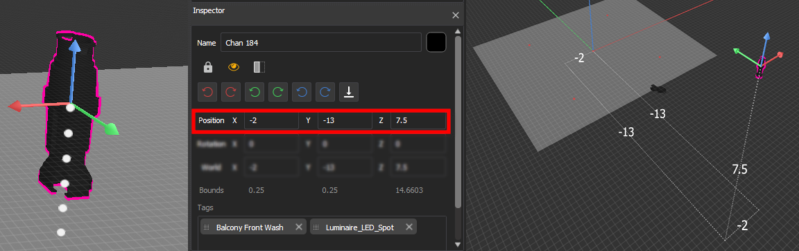
Position data is either local or world. For more information, see Inspector.
In the above example, the fixture patched to Channel 184 is -2 meters offset on the X axis, -13 meters offset on the Y axis, and 7.5 meters offset on the Z axis.
Orientation data reflects how the fixture is rotated. The values for X, Y, and Z represent a rotation in degrees around that axis in relation to the global XYZ axes.
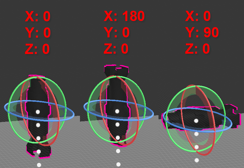
The above left example shows the default orientation of 0/0/0, or pointing straight down. The center shows a rotation of 180° about the X axis, pointing the fixture straight up. The final example shows a rotation of 90° about the Y axis, pointing the fixture to the side.
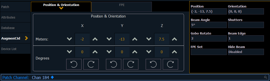
Under the Augment3d section in Patch, fixtures have fields for XYZ Position and Orientation. If the fixture is nested, this data is relative to the parent. World Position and Orientation are absolute, relative to the scene overall. If nested, an arrow indicator will apear next to the position and orientation fields. For more information about nesting, see Nesting Objects.
You can also edit the following additional properties:
Select the channel of a fixture for which you have position and orientation data, and navigate to the Position & Orientation section of the Augment3d tab in Patch. Selecting one of the position or orientation fields opens a keypad to input specific values.
Alternatively, keyboard syntax can be used. Use [/] to separate X, Y, and Z when typing in multiple values, and [Thru] to enter information for multiple fixtures at once.
All trailing slashes are optional. [Chan] [1] [Thru] [10] Position [5] [Thru] auto-completes to [Chan] [1] [Thru] [10] Position [5] [/] [*] [/] [*] [Thru].
The corresponding fixture is automatically added to the Augment3d model. Repeat the process for any additional channels or fixtures, or edit fixture position and rotation using tools available in the toolbar or the Inspector.
Position [@] [Enter] will remove the pose (position and orientation) of the selection. Orientation [@] [Enter] will reset the orientation of the selection to (0,0,0).
If you have a fixture with shutters, they must be configured in the Fixture Editor to display accurately in Augment3d.
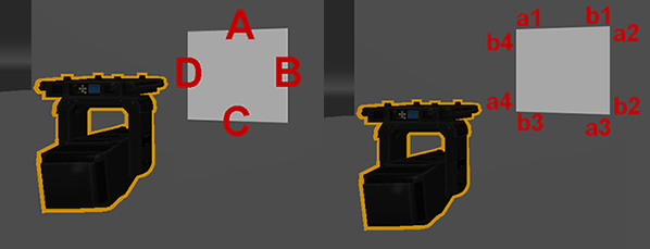
Standard shutter controls are now normalized relative to the square so that A controls the top edge, with controls B, C, and D continuing clockwise in that order.
Pushrod-style shutter parameters are normalized so that frame a1 corresponds to the counterclockwise side of the top edge and b1 to the clockwise side, with frames a2, b2, a3, b3, a4, and b4 continuing clockwise in that order.
If your fixture has a moving mirror accessory, it must be patched to a two-part channel, with P1 patched to an address as a dimmer and P2 as a moving mirror accessory.
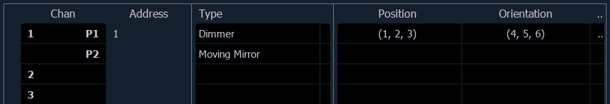
Position and orientation data for the fixture can only be added and edited in P1. Attempting to add position and orientation data to the entire channel will return a syntax error. The moving mirror can be controlled via the pan and tilt parameters for P2.
Regardless of the fixture and mirror type, the model will display in Augment3d as a Source Four with a generic mirror.
Fixture position and rotation can also be edited in Augment3d Edit Mode using tools available in the toolbar or in the Inspector.
Any changes made to fixture position in Augment3d will automatically update the values in Patch. Similarly, any change made via Patch will automatically update the fixtures in Augment3d.
The Orientation property for conventional (non-automated) fixtures is used to aim static lighting fixture at the correct point.
Navigate to Patch.
Note: You do not need to enter Augment3d Edit Mode to select fixtures.