Main Display Tabs

A small selection of common properties are displayed on each display tab, regardless of the device type.
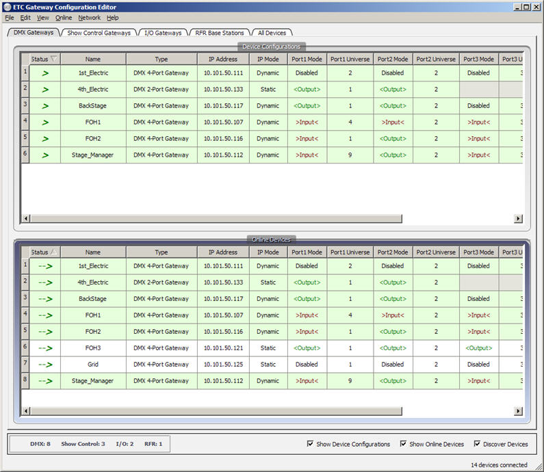
Status
The "Status" field displays the current status of the related device. Status icons will vary from the "Device Configurations" table to the "Online Devices" table. For a list of status icons see "Legend".
Name
The "Name" field is the name property of the device. This property can be set by the user by double-clicking in the "Name" field and typing text or right clicking inside the field and selecting "Edit Selected Cells" from the context menu. It is recommended that you use a unique name that differentiates each device from the other and their intended uses. Net3 DMX gateway's default to a unique name made up of the manufacturer, the gateway type, and the last half of its assigned MAC address. For example, ETCNet3GW4P00651f.
Type
Displays the device type. Examples are: DMX 4-Port Gateway, DMX 2-Port Gateway, Show Control Gateway, I/O Gateway and RFR Base Stations. Other types may be added in the future.
IP Address
The gateway device IP address is displayed for reference. To edit the device IP address, see "Edit Device Configuration".
IP Mode
Displays whether the IP address has been assigned a Dynamic IP address address (for example via DHCP address server) or has manually been given a Static IP address.
When this tab is selected, the table displays a subset of the properties for DMX Gateways.
Note: Reference "Common Properties for All Display Tabs" for details of common properties of this display not detailed below.

Port Mode
Displays the mode of a DMX port (ports are defined as 1 through 4 with port 1 on the left as you are looking at the rear of a Four-Port Gateway). Available modes include:
- Disabled - no DMX is received or transmitted
- >Input< - DMX is able to be received by this port
- <Output> - DMX is transmitted by this port
Port Universe
Displays the Universe number that the DMX port will either receive or transmit on the network. The range is from 1 to 63999 for Net3/ACN and 1 to 64 when using ETCNet2/eDMX.
When utilizing flexible output patch, port universe information will be displayed in standard sACN format (for example, universe/address:length).
Note: Each port and universe is represented separately in the table. When a universe value is greater than 63999, either as a property of, or part of an advanced input patch, that universe property display's in red until the addressing problem is corrected.
Network Address
You can choose to "Show..." or "Hide..." the Network Address column from the tables for DMX Gateways by selecting from the (View) menu. By default, the Network Address column is hidden. When shown, the Network Address for each port is displayed after the Port Universe column. Network Addresses are displayed as an eDMX style address.
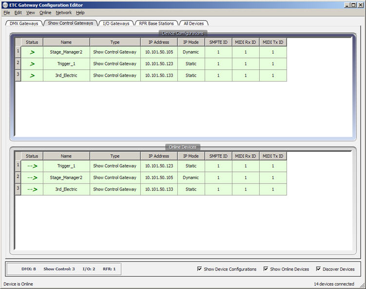
When the "Show Control Gateways" tab is selected, the table displays a subset of properties, specifically related to Show Control Gateway(s).
Note: Reference "Common Properties for All Display Tabs" for details of common properties of this display not detailed below.

SMPTE ID
The "SMPTE ID" property is a value (ranging from 0 to 32) that matches the value that is entered by a user into the control console "Show Control" settings. This value indicates that this SMPTE input port on the gateway is the communication port of SMPTE messages sent from the control console.
When initialized, the control console discovers the gateway and checks for a matching SMPTE ID to see if it should attach to the input and subscribe to the SMPTE input over ACN. A SMPTE port on a gateway only acts as an input port and converts a SMPTE signal into an ACN stream.
MIDI Rx ID
The "MIDI Rx ID" property is a value (ranging from 0 to 32) that matches the value that is entered by a user into the control console "Show Control" settings. This value indicates that this MIDI Rx input port on the gateway is the communication port of MIDI signals sent from the control console.
When initialized, the control console discovers the gateway and checks for a matching MIDI Rx ID to see if it should attach to the input and subscribe to the MIDI Rx input over ACN. A MIDI Rx port on a gateway only acts as an input port and converts a MIDI signal into an ACN stream.
MIDI Tx ID
The "MIDI Tx ID" property is a value (ranging from 0 to 32) that matches the value that is entered by a user into the control console "Show Control" settings. This value indicates that this MIDI Tx output port on the gateway is the communication port of MIDI Tx signals from ACN over Ethernet to a console or similar device.
When initialized, the control console discovers the gateway and checks for a matching MIDI Tx ID to see if it should attach to the output and subscribe to send MIDI Tx signals using ACN over Ethernet to a connected device.
Analog ID
The "Analog ID" field displays the Analog Group ID. An Analog Group ID is similar in concept to a DMX Universe, except that you can have 65535 addresses per "Analog ID". Each Analog input has an address (0 to 65535) within each Analog Group ID. Both the Analog Group ID and the Analog Address for a particular analog input are needed to access that information. The default "Analog ID" is 1, but the available range is from 0 to 32.
Relay ID
The "Relay ID" field displays the Relay Group ID. An Relay Group ID is similar in concept to a DMX Universe, except that you can have 65535 addresses per Relay Group ID. Each relay output has an address (0 to 65535) within each Relay Group ID. Both the Relay Group ID and the Relay Address for a particular relay output are needed to access and control that relay. The default "Relay ID" is 1, but the available range is from 0 to 32.
Serial ID
The "Serial ID" field displays the Serial Group ID. The Serial Group ID is used to identify a serial port on a gateway. A Serial Group ID also has a Serial Address, but this function is not currently supported. The default "Serial ID" is 1, but the available range is from 0 to 32.
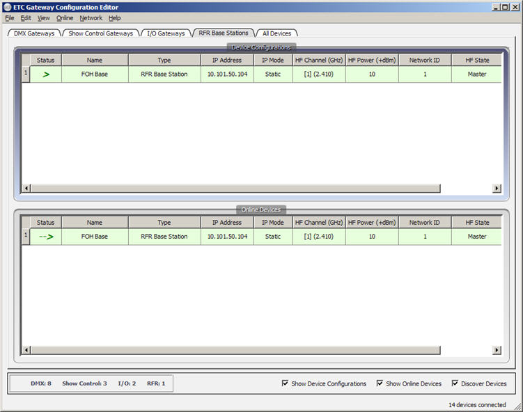
When the "RFR Base Stations" tab is selected, the table displays a subset of the properties specifically for Radio Focus Remote base stations.
Note: Reference "Common Properties for All Display Tabs" for details of common properties of this display not detailed below.

HF Channel (GHz)
The "HF Channel (GHz)" field is a click inside and pull-down menu used to set the channel for communication to an RFR handheld unit. The RFR handheld unit must be set to the same HF channel as the base station in order for the pair to function and communicate together.
HF Power (+dBm)
CAUTION: This value must be 10 when used in Europe.
The "HF Power (+dBm)" field is a pull-down menu used to set the base station's power level. This power level is noted in dBm (sometimes known as dBmW). The higher the dBm, the greater the signal strength. The lowest functional dBm setting should be used to avoid interference with other products.
Network ID
The "Network ID" field is provided to set a unique ID used to communicate between an RFR base station and RFR handheld unit. The handheld unit must be set to the same Network ID as the base station for the pair to communicate together. The "Network ID" range is from 1 to 99.
HF State
The "HF State" field is a pull-down menu used to set the state of an RFR base and handheld. Options include "Master" or "Slave".
- If you have a single handheld unit for use with a single base station, set the base station to "Master".
- If you have a single handheld unit for use with multiple base stations on the network, set only one base to "Master" and all others to "Slave".
A Master base station acts as the main base station to all other slave base stations on the network. The master gather's communication from the handheld as the handheld moves its connection between the multiple base stations and communicated directly with a Net3 console. A "Slave" base station must act in combination with a "Master" base station on a network to transmit information to a Net3 console.
