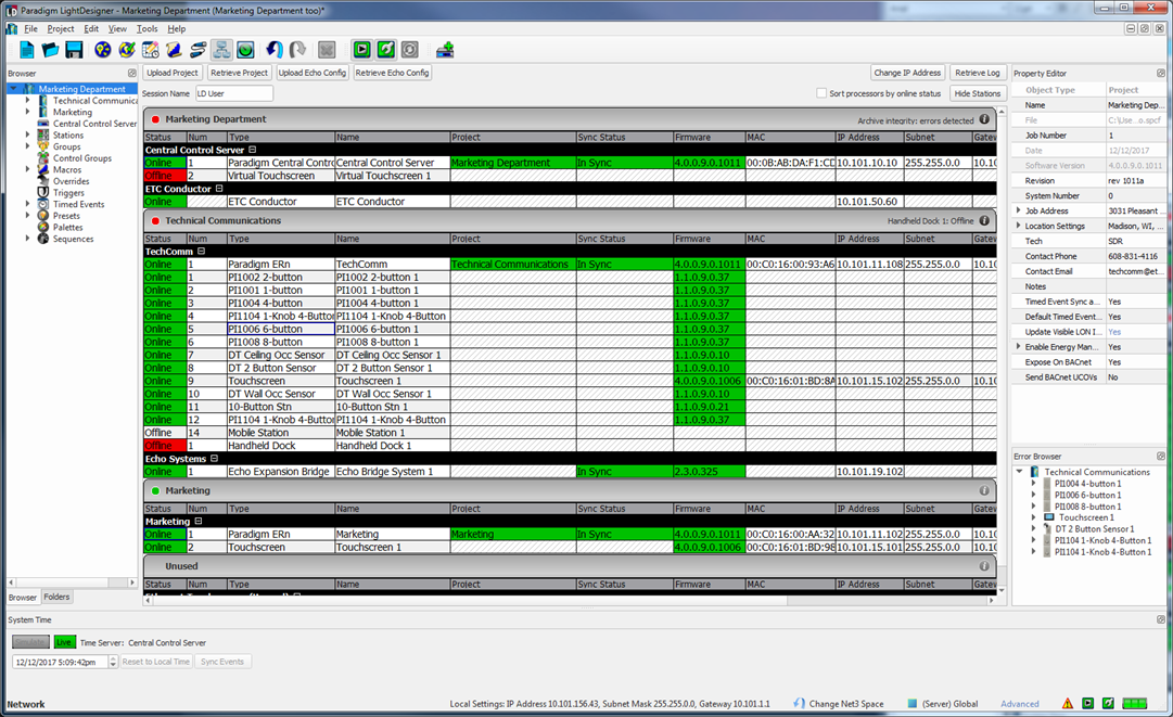
The Network view ![]() provides a device list which displays in tabular format all items that are either connected to or expected to be connected to the LightDesigner configuration, as well as any devices that are discovered on the network.
provides a device list which displays in tabular format all items that are either connected to or expected to be connected to the LightDesigner configuration, as well as any devices that are discovered on the network.
Each device and its network specific properties are provided a color coded highlight for visual representation of its status.
From the Network view you can:
All of the basic features that are found in other application views are also featured in the Network view, such as access to the Browser, Folders, Property Editor, System Time, and Error Browser.
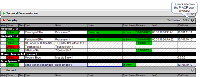
The device list provides a listing of all devices, including servers (if the configuration is a server project), processors and stations that are either already connected or expected to be connected (connected, meaning identified on the Paradigm network), as well as the devices that are discovered on the network but not found in the configuration.
Use the device list as a visual representation of the status of each device and its properties and use it to identify discovered stations (Lon devices) for association of their Neuron IDs to stations that are in the configuration (expected to be connected) when they do not automatically bind.
Any changes to the status of devices in the Network view, such as uploading a project, retrieving a project, changing an IP address, changing a Session Name, show or hide stations stations, and sort the processors by online status, are reflected in this device list.
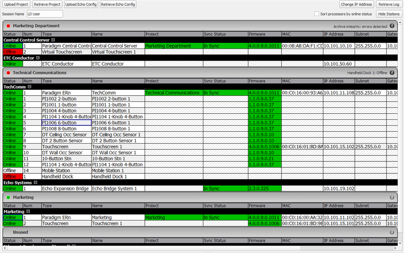
Each project that is included in the server project is represented in an individual section and include its own devices (very similar to how individual projects will display in a non-server project system). Projects will appear listed in the same order they are found in the Browser. Any "Unused" devices that are found on the network but are not expected in a project configuration will be represented at the bottom of the device list.
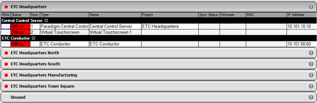
Server projects contain multiple projects (sub-projects) which are managed from a single configuration. Each project that is included in the server project is represented in an individual section in the Network view and includes its own devices (very similar to how individual projects will display in a non-server project system). Projects will appear listed in the same order they are found in the Browser. Projects can be collapsed or expanded within the Network view device list .
A server project orders the device list with the server level devices first; such as the Central Control Server (P-CCS) and any Virtual Touchscreen instances (if specified), as well as the ETC Conductor device. Projects will appear listed in the same order they are found in the Browser.
The Network view offers visual status of the System Components as well as individual devices and errors in discovered.
System component status displays at the header of each project component section in the device list. Identify at a glance the status of all components in the server project or sub-projects.
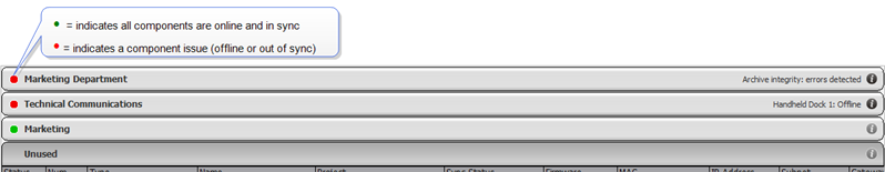
The system component status feature is most helpful when your system has many sub-projects, allowing you to collapse the headers and view status of each project much easier.
The device list displays status for the individual devices and many of their important parameters such as their sync status and firmware number. Status changes for devices are identified by the highlighted color of the important devices parameters.
Status Color Coding
Errors that are reported at the Paradigm Architectural Processor (P-ACP) user interface will also display at the project level in the Network view. A scrolling list of errors display in the same priority order as found on the P-ACP user interface and View / Clear Errors menu. The most severe errors are displayed first in the scrolling list.
Click the more information button ![]() on the status bar to display the list of errors for that project.
on the status bar to display the list of errors for that project.
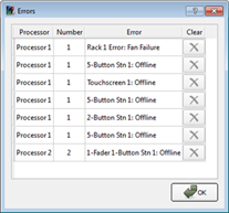
Some errors can be cleared from the list by clicking the "Clear" ![]() button next to the error message. If the error still exists after clearing, it will reappear in the list again until the condition is cleared. Other errors cannot be cleared and therefore the "Clear" button will be grayed and not selectable. When the conditions causing the errors are rectified, the errors will automatically clear themselves from the list.
button next to the error message. If the error still exists after clearing, it will reappear in the list again until the condition is cleared. Other errors cannot be cleared and therefore the "Clear" button will be grayed and not selectable. When the conditions causing the errors are rectified, the errors will automatically clear themselves from the list.
Send a wink command to a detected or connected and "Online" station or device found in the device list to help physically identify the device in a space. This feature is very useful to identify a device that is not labeled with a Neuron id and to identify devices that did not automatically bind initially in the configuration. To send a wink command for a specific device, right-click on the device in the device list and select "Wink Station" from the context menu.
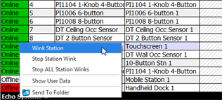
LightDesigner sends a command to the connected device to perform a visual action for identification in an installed space. For example, a Unison Paradigm Inspire station will blink all LED's in a red, green, blue cycle; however the specific behavior is determined by the manufacturer of the Lon based device.
For a Paradigm Inspire, Dual Tech Occupancy Sensor, or Heritage control station, pressing any button on the station causes the Wink Station command to terminate and will bind the station to the LightDesigner configuration.
The "Stop Station Wink" command is available to Paradigm Inspire stations, Paradigm Dual Tech Occupancy Sensors and Stations, and Paradigm 7" Touchscreens only.